https://www.multisim.com/content/AU6RuewqYG4AuExbtUEogf/week-10-lab-lesson-aidan-singh/open/
3 Pedals I find Interesting:
It is important to note first that I am not a guitar player, and that might be reflected in the pedals I chose.
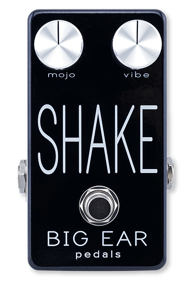
This pedal is interesting in that it can be used to trigger/add an instrumental layer live. This can be done regardless of if you are already playing an instrument.
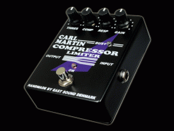
I didn’t know compressors/limiters were common guitar pedals. This one was especially cool because it has the same controls as the studio/plugin compressors I’ve used.
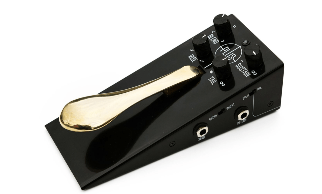
Lastly, this sostenuto pedal made me rethink what pedals are supposed to do, as this resembles a piano sus pedal to me more than a guitar pedal, reflecting its purpose.
1B.) From my understanding, the large companies in guitar pedal manufacturing tend to make the typical or essential pedals, such as reverb and distortion, at a standard or quality level. Other manufacturers tend to make pedals with a more niche sound, more niche effects, or more niche price points (above or below industry standard).
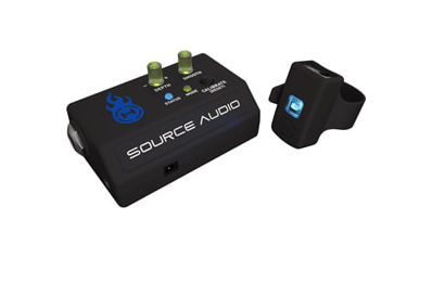
1C.) This pedal, although definitely partly Digital, is controlled by a gesture sensing device to be worn on a wrist. I thought this was very cool.
2.)An SP5T switch is a switch with multiple routing options (5 outputs)
3.) A latching button functions as a switch that flips when you press it, and stays flipped when you let go. This would be good for an on/off button. A momentary button functions as a break in the circuit that completes itself when the button is pressed in, and not when it is out. It would be good for an effect that you only want in certain parts of a performance, such as a vibrato.
Aidan Singh
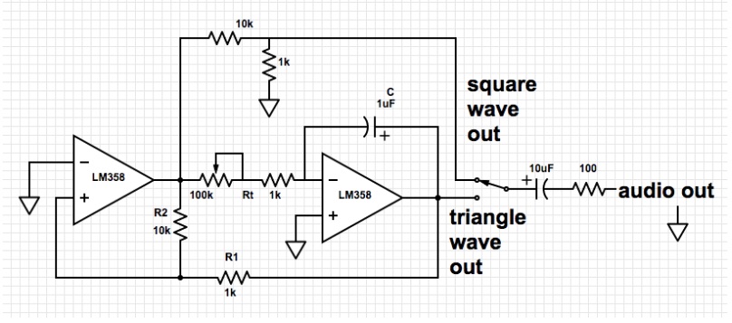
Output Frequency = (1/(4*Rt*C)) * (R2/R1)
Output Frequency (min) = (1/(4*1000*1)) * (10000/1000)
= 400 [Hz]
Output Frequency (max) = (1/(4*11000*1)) * (10000/1000)
= 4400 [Hz]
Range (approx.) = 400 [Hz] – 4400 [Hz]
LOW PASS FILTER
Corner Frequency(min)= 1/(2(pi)(10)(.000001))
=15.915 [Hz]
Corner Frequency(max)= (2(pi)(10000)(.000001))
=15915.494 [Hz]
Range (approx.) = 15[Hz] – 15[kHz]
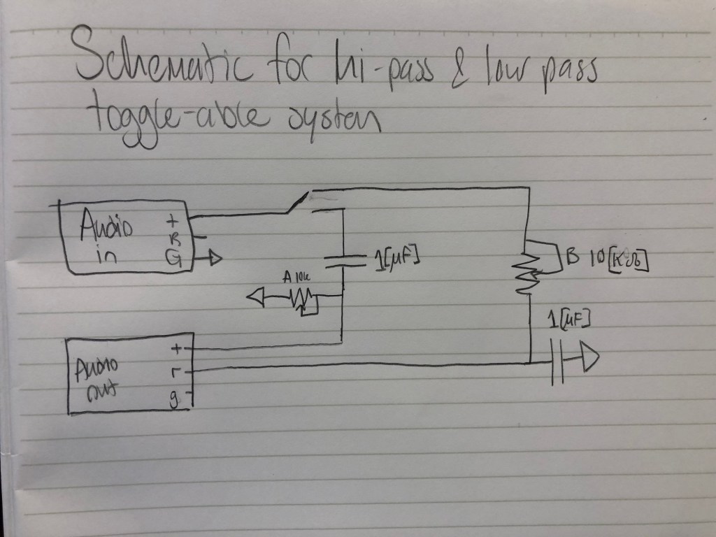
HIGH PASS FILTER (right circuit), TOGGLE-ABLE HIGH & LOW PASS FILTERS
Corner Frequency(min)= 1/(2(pi)(10)(.000001))
=15.915 [Hz]
Corner Frequency(max)= (2(pi)(10000)(.000001))
=15915.494 [Hz]
Range (approx.) = 15[Hz] – 15[kHz]
Part 4: You can create a steeper filter by putting 2 equivalent filters in series!
Part 5: idea for final project: make a “bass boost” box that splits an analog signal, then low passes one, then adds them again.
Complicated idea for final project: make a “slow and reverb” box, following the trend of doing slowed and reverb-ed songs on youtube.
Another Idea: make a “noise cancelling” box for headphones, that mic’s the room sound, inverts the signal, and adds it to the audio.
It would be cool to know how manipulatable drum machines work.
EXTRA CREDIT:
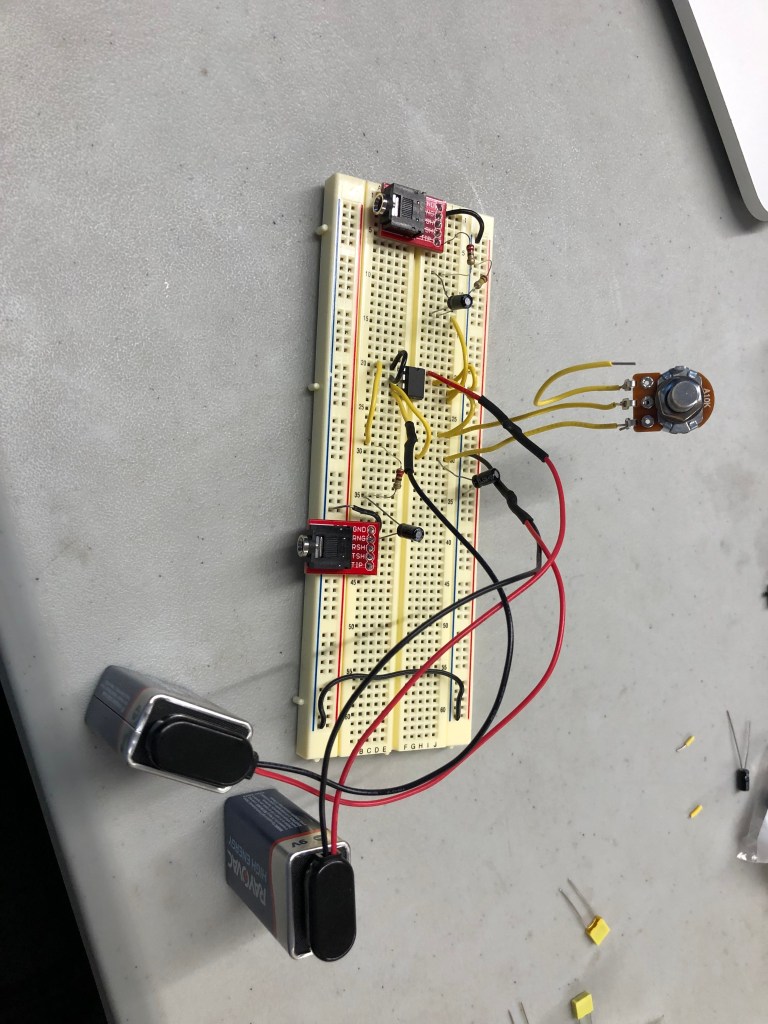
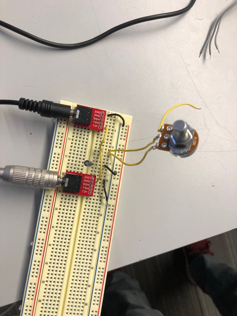
Headphone Compatible Low-Pass Filter
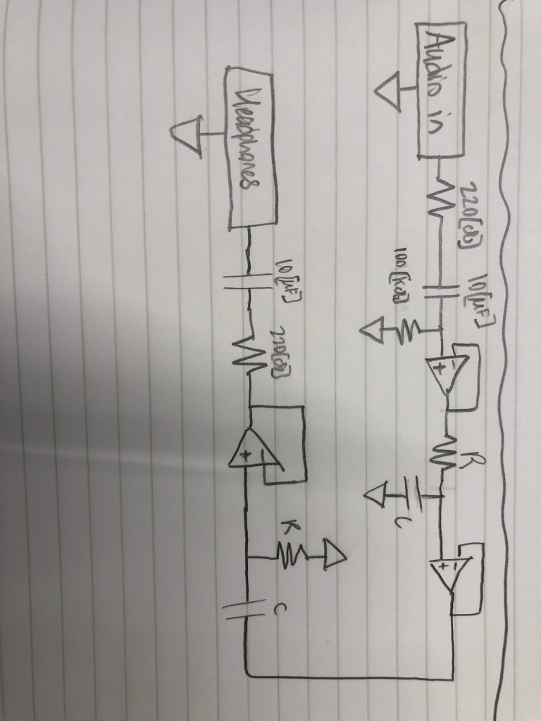
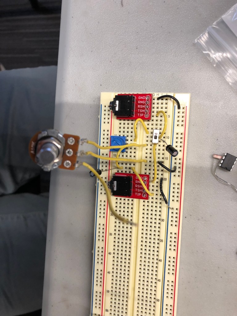
Buffered Circuit with High & Low pass filters in series (sorry for sideways, I couldn’t fix this in WordPress)
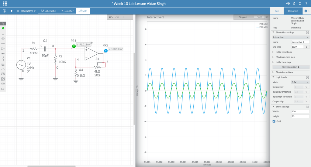
For this lab, we used operational amplifiers for the first time.
Adding a resistor and capacitor in the beginning of this circuit (after the audio input) protected the audio jack in case a DC voltage came from improper circuit wiring.
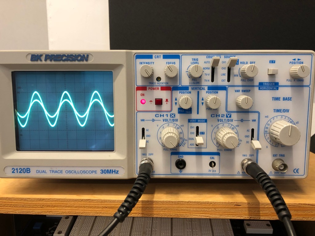
This is the oscilloscope after making the initial op amp circuit, which wasn’t inverting and used two equivalent resistors to make a voltage divider, so the gain would be 2.
This is the non inverting circuit with a potentiometer replacing the feedback resistor
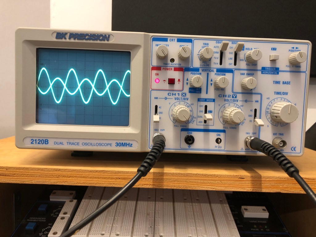
This is the oscilloscope after making the second op amp circuit, which inverted and amplified the signal.
This is an inverting op amp circuit with a potentiometer for the feedback resistor.
This is the inverting signal with a photocell (light determined resistor) replacing the feedback resistor.
The spark fun data sheet for this photocell shows that the maximum resistance, which is the resistance in darkness, is 10k [ohms], and the minimum resistance (full light) is 1k [ohms].
Since this is an inverting circuit, the gain determined by the ratio of Rf/Rin.
Because Rf can go from 1k – 10k [ohms], and Rin was 4.7k [ohms], the minimum gain was approximately .213 (the output sound would be quieter than the input), and the maximum gain would be 2.128 (louder than the input).
Since in the video I didn’t put the photocell in complete darkness or under bright light, the gain was in-between these values.
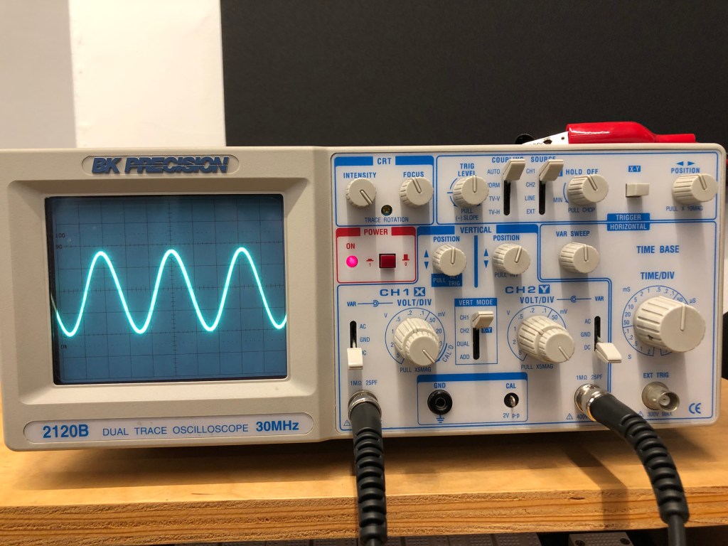
To get the sine wave I input from my phone to display on the screen, I had to learn and adjust a variety of settings on this oscilloscope.
Firstly, we were working with a DC signal, and I was sending the signal through channel 1, so I set the input and voltage source accordingly.
The intensity and focus pots are used to adjust the brightness and sharpness of the line displayed on the screen, respectively.
The voltage per division pot changes the unit of the vertical graphic divisions, or the amplitude of the wave displayed.
The time per division pot changed the unit of the horizontal graphic divisions, or the period of the wave displayed.
The trigger level regulated how the oscilloscope sampled and displayed the waves, and setting it dictated if the wave was flickery or solid, the location of the wave, and the source of the wave.
The position pot moved the wave displayed along the x axis, and I used it to center the wave.
When using the potentiometer, the maximum amplitude as a proportion of the input wave was 1:1. The minimum amplitude was 0.
Soldering Preparation
Before you walk away from the soldering iron…
Before using a multimeter…