Digital Lab 5

Aidan Singh

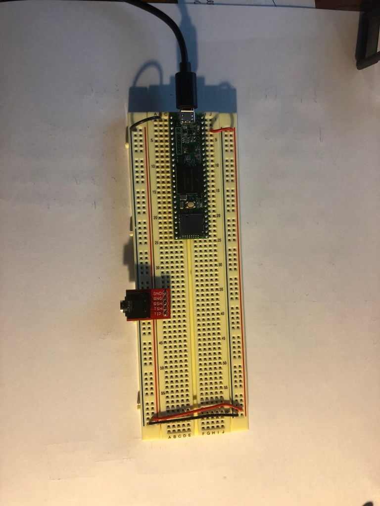
This is a step sequencer that like lab 4 has potentiometers that control the pitches, an octave switch, and an on-off switch. In addition to this, it has a new forwards/reverse switch for the playing order of potentiometers/pitches, and a number potentiometer determining how many steps are in the sequencer [BONUS].

The code utilizes arrays and for loops to condense much of the previous code from lab 4.


//pins
int potPins[4] = {33, 34, 35, 36};
int speedPotPin = A13;
int ledPins[4] = {28, 29, 30, 31};
int octaveSwitchPin = 37;
int onSwitchPin = 38;
int backwardsSwitchPin = 39;
int BONUSPOT = A21;
int bonusValue = 0;

//values
int speedPotValue=100;
int pitches[4] = {0, 0, 0, 0};
int octave= 0;

void setup() {
    Serial.begin(9600);
    for(int i=0; i<4; i++){
      pinMode(ledPins[i], OUTPUT);
    }
     pinMode(octaveSwitchPin, INPUT);
     pinMode(onSwitchPin, INPUT);
     pinMode(backwardsSwitchPin, INPUT);
}


void loop() {
  if(digitalRead(onSwitchPin) == HIGH) {
    if(digitalRead(backwardsSwitchPin) == HIGH){
      sequenceForwards();
    }
    else{
      sequenceBackwards();
    }
  }
}

void sequenceForwards(){
  bonusValue = map(analogRead(BONUSPOT), 0, 1023, 0, 3);
  speedPotValue = map(analogRead(speedPotPin), 0, 1023, 100, 1000);
  if(digitalRead(octaveSwitchPin) == HIGH) {
    octave=12;
  }if(digitalRead(octaveSwitchPin) == LOW) {
    octave=0;
  }

  for(int i=0; i<4; i++){
      pitches[i] = map(analogRead(potPins[i]), 0, 1023, 60, 72)+octave;
    }                              
  
  /*the pitches above are set according to their
 respective potentiometers, and made an octave higher
 based on the value of the int "octave"*/
 
  for(int i=0; i<=bonusValue; i++){
    digitalWrite(ledPins[i], HIGH);
    note(pitches[i], speedPotValue);
    digitalWrite(ledPins[i], LOW);
    }        
}

void sequenceBackwards(){
  bonusValue = map(analogRead(BONUSPOT), 0, 1023, 0, 3);
  speedPotValue = map(analogRead(speedPotPin), 0, 1023, 100, 1000);
  if(digitalRead(octaveSwitchPin) == HIGH) {
    octave=12;
  }if(digitalRead(octaveSwitchPin) == LOW) {
    octave=0;
  }

  for(int i=0; i<4; i++){
      pitches[i] = map(analogRead(potPins[i]), 0, 1023, 60, 72)+octave;
    }                              
  
  /*the pitches above are set according to their
 respective potentiometers, and made an octave higher
 based on the value of the int "octave"*/
 
  for(int i=bonusValue; i>=0; i--){
    digitalWrite(ledPins[i], HIGH);
    note(pitches[i], speedPotValue);
    digitalWrite(ledPins[i], LOW);
    }        
}

void note(int pitch, int speeed){  //simplifies playing a [pitch] for [speeed] amount of time
  usbMIDI.sendNoteOn(pitch,90,1);
  delay(speeed);
  usbMIDI.sendNoteOff(pitch,0,1);
}

Digital Lecture 3

Aidan Singh

Part 1: A Better Synth

This synth is different from the previous ones I’ve made in that it is polyphonic, has a variable sustain, and no perceivable delay. This is due to the use of if statements that check for the exact moment a button is pressed and released to send MIDI information, rather than using delays to turn off MIDI notes.


int ledPin1 = 28;
int ledPin2 = 29;
int ledPin3 = 30;
int ledPin4 = 31;
int buttonPin1 = 33;
int buttonPin2 = 34;
int buttonPin3 = 35;
int buttonPin4 = 36;
bool buttonState1= LOW;
bool lastButtonState1= LOW;
bool buttonState2= LOW;
bool lastButtonState2= LOW;
bool buttonState3= LOW;
bool lastButtonState3= LOW;
bool buttonState4= LOW;
bool lastButtonState4= LOW;

void setup() {
    Serial.begin(9600);

    pinMode(ledPin1, OUTPUT);
    pinMode(ledPin2, OUTPUT);
    pinMode(ledPin3, OUTPUT);
    pinMode(ledPin4, OUTPUT);

    pinMode(buttonPin1, INPUT);
    pinMode(buttonPin2, INPUT);
    pinMode(buttonPin3, INPUT);
    pinMode(buttonPin4, INPUT);

}

void loop() {
  checkButtons();

}

void checkButtons(){
  checkButton1();
  checkButton2();
  checkButton3();
  checkButton4();
  
}

void checkButton1(){
  lastButtonState1=buttonState1;
  buttonState1=digitalRead(buttonPin1);
  if( (buttonState1 == HIGH) and (lastButtonState1 == LOW)){
    usbMIDI.sendNoteOn(60, 90, 1);
    digitalWrite(ledPin1, HIGH);
    delay(5);
  } else if (lastButtonState1 == HIGH and buttonState1== LOW){
    usbMIDI.sendNoteOff(60, 0, 1);
    digitalWrite(ledPin1, LOW);
    delay(5);
  }
}

void checkButton2(){
  lastButtonState2=buttonState2;
  buttonState2=digitalRead(buttonPin2);
  if( (buttonState2 == HIGH) and (lastButtonState2 == LOW)){
    usbMIDI.sendNoteOn(64, 90, 1);
    digitalWrite(ledPin2, HIGH);
    delay(5);
  } else if (lastButtonState2 == HIGH and buttonState2== LOW){
    usbMIDI.sendNoteOff(64, 0, 1);
    digitalWrite(ledPin2, LOW);
    delay(5);
  }
}

void checkButton3(){
  lastButtonState3=buttonState3;
  buttonState3=digitalRead(buttonPin3);
  if( (buttonState3 == HIGH) and (lastButtonState3 == LOW)){
    usbMIDI.sendNoteOn(67, 90, 1);
    digitalWrite(ledPin3, HIGH);
    delay(5);
  } else if (lastButtonState3 == HIGH and buttonState3 == LOW){
    usbMIDI.sendNoteOff(67, 0, 1);
    digitalWrite(ledPin3, LOW);
    delay(5);
  }
}

void checkButton4(){
  lastButtonState4=buttonState4;
  buttonState4=digitalRead(buttonPin4);
  if( (buttonState4 == HIGH) and (lastButtonState4 == LOW)){
    usbMIDI.sendNoteOn(72, 90, 1);
    digitalWrite(ledPin4, HIGH);
    delay(5);
  } else if (lastButtonState4 == HIGH and buttonState4 == LOW){
    usbMIDI.sendNoteOff(72, 0, 1);
    digitalWrite(ledPin4, LOW);
    delay(5);
  }
}


Part 2: Demonstrating Better Potentiometer Use

int potVal = 0;
int lastPotVal = 0;


void setup() {
  Serial.begin(9600);

}

void loop() {
  lastPotVal = potVal;
  potVal = map(analogRead(A13), 0 , 1023, 0, 10);
  if(potVal != lastPotVal) {
    Serial.println(potVal);
    delay(10);
  }
}

Digital Lab 4

Aidan Singh

See comments in code for explanation


int speedPotPin=A13;
int pot1 = 33;
int pot2 = 34;
int pot3 = 35;
int pot4 = 36;

int speedPotValue=100;

int ledPin1 = 28;
int ledPin2 = 29;
int ledPin3 = 30;
int ledPin4 = 31;

int switchPin = 37;
int switchPin2 = 38;

int pitch1= 0;
int pitch2= 0;
int pitch3= 0;
int pitch4= 0;

int octave= 0;

void setup() {
    Serial.begin(9600);
    pinMode(ledPin1, OUTPUT);
    pinMode(ledPin2, OUTPUT);
    pinMode(ledPin3, OUTPUT);
    pinMode(ledPin4, OUTPUT);
    pinMode(switchPin, INPUT);
    pinMode(switchPin2, INPUT);
}


void loop() {
  if(digitalRead(switchPin2) == HIGH) {     //This if statement checks the "on" switch,
    arpeggio();                             //and only runs arpeggio() if on
  }
}


void arpeggio(){
  
  speedPotValue = map(analogRead(speedPotPin), 0, 1023, 100, 1000);
  
  if(digitalRead(switchPin) == HIGH) {
    octave=12;
  }
  if(digitalRead(switchPin) == LOW) {
    octave=0;
  }
  
  /*The previous if statements determine
  the octave from the octave switch*/
                                            
  pitch1= map(analogRead(pot1), 0, 1023, 60, 72)+octave;
  pitch2= map(analogRead(pot2), 0, 1023, 60, 72)+octave;
  pitch3= map(analogRead(pot3), 0, 1023, 60, 72)+octave;
  pitch4= map(analogRead(pot4), 0, 1023, 60, 72)+octave;
  
  /*the pitches above are set according to their
 respective potentiometers, and made an octave higher
 based on the value of the int "octave"*/
 
  digitalWrite(ledPin1, HIGH);
  note(pitch1, speedPotValue);
  digitalWrite(ledPin1, LOW);

  digitalWrite(ledPin2, HIGH);
  note(pitch2, speedPotValue);
  digitalWrite(ledPin2, LOW);
  
  digitalWrite(ledPin3, HIGH);
  note(pitch3, speedPotValue);
  digitalWrite(ledPin3, LOW);
  
  digitalWrite(ledPin4, HIGH);
  note(pitch4, speedPotValue);
  digitalWrite(ledPin4, LOW);

  //Pitches play in order, LED's blink in order

}


void note(int pitch, int speeed){  //simplifies playing a [pitch] for [speeed] amount of time
  usbMIDI.sendNoteOn(pitch,90,1);
  delay(speeed);
  usbMIDI.sendNoteOff(pitch,0,1);
}


Digital Lecture 2

Aidan Singh

Errors In the Code

  1. No semicolon after declaring a new variable (int buttonPin)
  2. Void Setup never set the second LED and button pins as inputs or outputs.
  3. The main void loop never used the function checkButton2()

https://www.tinkercad.com/things/h5NPnybvAzS

Code Explanation

  • Function 1 will cycle through the LED’s whose switches are on, and blink them in order. This is due to the sequential if statements checking each switch, each containing a delay, so that once the leftmost switch is checked, it blinks the LED THEN checks the one to its right next.
  • Function 2 only blinks the leftmost button that’s turned on. This is due to the use of else if statements, which only checks the remaining switches if the prior if statements are false.
  • Function 3 blinks all LED’s whose switches are on. This is due to the use of sequential if statements and a delay that’s used after all the if statements turn on the corresponding LED’s.

Code Simplification

https://www.tinkercad.com/things/kB12VKMnxQl

Digital Lab 3

Aidan Singh

The distinction between the arpeggiator + keyboardd and arpeggiatorMode + keyboardMode functions is that the first two take an integer as an input and have no relation to buttons being pressed, and the “Mode” functions read the buttons and activate the first functions with pitches according to the inputs.

int potValue=0;

int ledPin1 = 28;
int ledPin2 = 29;
int ledPin3 = 30;
int ledPin4 = 31;

int pause=0;

int buttonPin1 = 33;
int buttonPin2 = 34;
int buttonPin3 = 35;
int buttonPin4 = 36;
int buttonPin5 = 37;
int buttonPin6 = 38;

void setup() {
    Serial.begin(9600);
    
    pinMode(ledPin1, OUTPUT);
    pinMode(ledPin2, OUTPUT);
    pinMode(ledPin3, OUTPUT);
    pinMode(ledPin4, OUTPUT);

    pinMode(buttonPin1, INPUT);
    pinMode(buttonPin2, INPUT);
    pinMode(buttonPin3, INPUT);
    pinMode(buttonPin4, INPUT);
    pinMode(buttonPin5, INPUT);
    pinMode(buttonPin6, INPUT);
    
}

void arpeggio(int note){
  pause = potValue;
  
  usbMIDI.sendNoteOn(note,90,1);
  digitalWrite(ledPin1, HIGH);
  delay(pause);
  digitalWrite(ledPin1, LOW);
  usbMIDI.sendNoteOff(note,0,1);
  
  usbMIDI.sendNoteOn(note+4,90,1);
  digitalWrite(ledPin2, HIGH);
  delay(pause);
  digitalWrite(ledPin2, LOW);
  usbMIDI.sendNoteOff(note+4,0,1);
  
  usbMIDI.sendNoteOn(note+7,90,1);
  digitalWrite(ledPin3, HIGH);
  delay(pause);
  digitalWrite(ledPin3, LOW);
  usbMIDI.sendNoteOff(note+7,0,1);
  
  usbMIDI.sendNoteOn(note+11,90,1);
  digitalWrite(ledPin4, HIGH);
  delay(pause);
  digitalWrite(ledPin4, LOW);
  usbMIDI.sendNoteOff(note+11,0,1);
  
}

void keyboardd(int note){

    usbMIDI.sendNoteOn(note,90,1);
    delay(pause);
    usbMIDI.sendNoteOff(note,0,1);
  
}

void arpeggiatorMode(){
  potValue = analogRead(A13);
  pause = potValue;

  int octave = 0;
    if(digitalRead(buttonPin6) == HIGH) {
    octave=12;
  }

  if(digitalRead(buttonPin1) == HIGH) {
    arpeggio(60+octave);
  }
  if(digitalRead(buttonPin2) == HIGH) {
    arpeggio(64+octave);
  }
  if(digitalRead(buttonPin3) == HIGH){
    arpeggio(67+octave);
  }
  if(digitalRead(buttonPin4) == HIGH){
    arpeggio(71+octave);
  }
}

void keyboardMode(){
  potValue = analogRead(A13);
  pause = potValue;

  int octave = 0;
    if(digitalRead(buttonPin6) == HIGH) {
    octave=12;
  }

  if(digitalRead(buttonPin1) == HIGH) {
    digitalWrite(ledPin1, HIGH);
    keyboardd(60+octave);
    digitalWrite(ledPin1, LOW);
  }
  if(digitalRead(buttonPin2) == HIGH) {
    digitalWrite(ledPin2, HIGH);
    keyboardd(64+octave);
    digitalWrite(ledPin2, LOW);
  }
  if(digitalRead(buttonPin3) == HIGH){
    digitalWrite(ledPin3, HIGH);
    keyboardd(67+octave);
    digitalWrite(ledPin3, LOW);
  }
  if(digitalRead(buttonPin4) == HIGH){
    digitalWrite(ledPin4, HIGH);
    keyboardd(71+octave);
    digitalWrite(ledPin4, LOW);
  }
  
  
}

void loop(){
  if(digitalRead(buttonPin5) == HIGH){
    keyboardMode();
  }
  if(digitalRead(buttonPin5) == LOW){
    arpeggiatorMode();
  }
}

Digital Lecture 1

Aidan Singh

https://www.tinkercad.com/things/dcMZmXhofvR

5 “Unique” Changes:

  1. This circuit is mainly different within the code when the button is pushed. When the button held down, the two white lights flash once, pause, flash twice fast, pause, flash twice three times, pause, and so on. If the button is released and pressed again, the counter starts at 1 again.
  2. I found that it was much easier to see the flashing if the two lights weren’t blue and green, rather white. Those colors seem to be worse for fast flashing/blinking.
  3. I also changed the color of some wires and the other LED just to familiarize myself with that function, with no other purpose.
  4. I also messed with the purple wire to familiarize myself with the location/curve function with no other purpose.
  5. Lastly I moved the resistor with no purpose.

Digital Lab 2

Aidan Singh

Part 1: Properly Wired Teensy

Part 2: Getting LED to work

Part 3: Digital input and output: Button and LED

Part 3 Continued: Switch instead of button

Part 4: Using Serial Monitor

Part 5: Using a potentiometer with Analog Input/Read

Part 6! (EXTRA CREDIT INCLUDED)

int potValue=0;

int ledPin1 = 28;
int ledPin2 = 29;
int ledPin3 = 30;
int ledPin4 = 31;

int pause=0;

int buttonPin1 = 33;
int buttonPin2 = 34;
int buttonPin3 = 35;
int buttonPin4 = 36;

int someVar= 0;


void setup() {
    Serial.begin(9600);
    
    pinMode(ledPin1, OUTPUT);
    pinMode(ledPin2, OUTPUT);
    pinMode(ledPin3, OUTPUT);
    pinMode(ledPin4, OUTPUT);

    pinMode(buttonPin1, INPUT);
    pinMode(buttonPin2, INPUT);
    pinMode(buttonPin3, INPUT);
    pinMode(buttonPin4, INPUT);
}

void loop(){
  potValue = analogRead(A13);
  pause = potValue;

  if(digitalRead(buttonPin1) == HIGH) {
    digitalWrite(ledPin1, HIGH);
    digitalWrite(ledPin2, HIGH);
    digitalWrite(ledPin3, HIGH);
    digitalWrite(ledPin4, HIGH);

    delay(pause);

    digitalWrite(ledPin1, LOW);
    digitalWrite(ledPin2, LOW);
    digitalWrite(ledPin3, LOW);
    digitalWrite(ledPin4, LOW);

    delay(pause);
  }
  
  if((digitalRead(buttonPin2) == HIGH) && (digitalRead(buttonPin3) == HIGH)) {
    digitalWrite(ledPin1, HIGH);
    delay(pause);
    digitalWrite(ledPin1, LOW);
    digitalWrite(ledPin2, HIGH);
    delay(pause);
    digitalWrite(ledPin2, LOW);
    digitalWrite(ledPin3, HIGH);
    delay(pause);
    digitalWrite(ledPin4, HIGH); 
    digitalWrite(ledPin3, LOW);
    delay(pause);
    digitalWrite(ledPin4, LOW); 
  }

  if((digitalRead(buttonPin2) == HIGH) && (digitalRead(buttonPin3) == LOW)) {
    digitalWrite(ledPin4, HIGH);
    delay(pause);
    digitalWrite(ledPin4, LOW);
    digitalWrite(ledPin3, HIGH);
    delay(pause);
    digitalWrite(ledPin3, LOW);
    digitalWrite(ledPin2, HIGH);
    delay(pause);
    digitalWrite(ledPin2, LOW); 
    digitalWrite(ledPin1, HIGH);
    delay(pause);
    digitalWrite(ledPin1, LOW); 
  }
  
  if(digitalRead(buttonPin4) == HIGH){
    someVar = random(28, 32);
    digitalWrite(someVar, HIGH);
    delay(pause);
    digitalWrite(someVar, LOW);
  }
}


Digital Lab 1

5 Previous Digital Electronics Projects I Like

  1. “LED Step Sequencer” – Samuel Pachon

https://treesapelectronics.wordpress.com/2017/12/15/final-project-digital-electronics-manateeseq/

This is a “Step Sequencer”, which is a grid that is used to visualize and place triggers for sounds. It repeats after a 4 beat count, and has a potentiometer controlling the tempo. It has two joysticks that are used to place the triggers/notes, opposed to performing and playing the notes to be recorded. This means the sounds will fall exactly on the beat every time.

2. “The Singing Glock” – Ethan Bailey

The Singing glock is a glockenspiel that has electronic hammers that are triggered by a Microcontroller. The Microcontroller determines when to play a note and which note to play from an audio input with a mic intended to be sung into.

3. Mapping Sound Waves- Hank Borders

https://hankborders.wordpress.com/2018/12/12/digital-lab-13-final-project/

This project uses a Microcontroller to take an audio input and graphically represent it by drawing it. It uses a servo motor to move a pen, which if dragged across a piece of paper, shows the amplitude of the wave over time. This project opened my mind to project possibilities beyond synthesizing or triggering sound.

4. “The Drum Glove” – Yasmin Williams

http://yazmelodies.blogspot.com/2015/12/final-project-report-drum-glove.html

The Drum Glove uses a glove with buttons and sensors to trigger drum sounds when pressed in certain areas. The most impressive part of this project was how he was able to play the drum sounds while playing the guitar, so the glove appeared to give him more flexibility with creating and performing.

5. “Teensy E-Cajon” – Max Chidzero

https://maximumcircuits.wordpress.com/2018/05/02/final-project-report/

The Teensy E-Cajon is a modified Cajon (a percussive instrument which looks like a box) with sensors that trigger sounds on a computer. This project interested me because of the prospect of modifying existing instruments. This is of interest to me because I am proficient at the violin but this isn’t necessarily applicable to creating notes for synthesis etc.

My Project Idea:

Analog Lab Week 13 Assignment

3 Compelling Digital Final Projects

The GrainCube– Paul Odenwaldt

This project was the most fascinating to me. Basically every other project was focused on triggering recorded sounds, physical instruments, or other sensory (e.g. visual) effects.

Unlike those, the GrainCube is an interactive physical device that synthesizes new sound as a granular synthesizer, not triggering an external synthesis device.

It had enough functionality that you have ease of control over what sound is being used for synthesis, its duration, pitch, delay effects, and more.

Drum Sequencer– Shane Patterson

This was one of the best interfaces for a sequencer I saw out of the projects. It made intuitive sense, like a DAW, to have the buttons light up sequentially from left to right, with time being represented as sliding across the buttons and playing the selected ones.

I am fascinated by physical DAW’s and sequencers because I think the constraint of their physical functionality directs and inspires what art comes from it.

I might want to make something very similar, but to have many time signatures. I haven’t seen that done yet. Or even to have different instruments be able to play polyrhythms, like to have the hats do sixteenth note triplets.

The Singing Glock– Ethan Bailey

There were a couple reasons I liked this project.

One being that ease of use/intuitive design was paramount. I didn’t find this to be a common trait of the other projects.

Another being that the video demo appeared effortless, comical, and creative, but was actually very concise and communicated its benefit well.

Arduino Based Projects

Pocket Synthhttps://create.arduino.cc/projecthub/etiennedesportes/pocket-synthesizer-785b50?ref=tag&ref_id=music&offset=100

This inspired me in how complete and compact it is. It looks like a real product someone would buy, doesn’t need external power, and has functionality all as if it wasn’t an amateur project.

Send All Messages– Link has been terminated, personal project

As a final technology course at my high school, we had the open ended prompt of determining an issue that we could create a technical solution for, as long as it was testable. We had the year to complete the assignment.

We chose the issue of communication during a school lockdown, which had to be silent yet trustable and robust. We used Arduinos, transceivers, and 16×2 LCD’s that could receive pre-made messages from a sending Arduino-transceiver system. I was tangentially involved in coding and circuit building, but my personal tasks involved using Inventor auto-CAD to design and CNC a box that could house the components, held the LCD, buttons, and antenna, and had ventilation. I also found the legal precedent for such a device.

(Question 3)

In digital electronics a button is a digital input, a potentiometer is an analog input, and an LED is an analog output.

(Question 4: Have I done any coding outside of NYU?)

In addition to working with Arduino’s as mentioned above, I took 3 computer science courses at my high school, learning rudimentary python, and taking AP comp. sci based in Java, where I scored 4/5 on the AP exam. This covered class and object use, sorting algorithms, and using libraries (mainly graphic ones).

I have also used auto CAD variants to produce G-code as mentioned above.

Design a site like this with WordPress.com
Get started