For this lab, we used operational amplifiers for the first time.
Adding a resistor and capacitor in the beginning of this circuit (after the audio input) protected the audio jack in case a DC voltage came from improper circuit wiring.
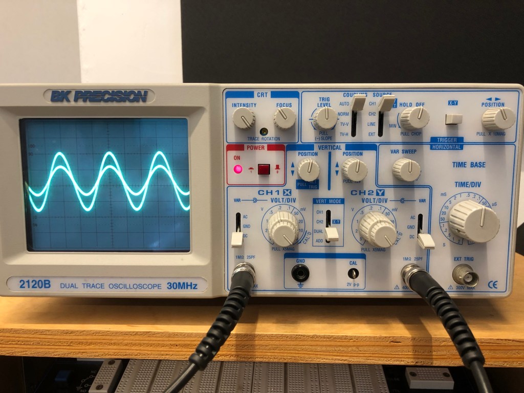
This is the oscilloscope after making the initial op amp circuit, which wasn’t inverting and used two equivalent resistors to make a voltage divider, so the gain would be 2.
This is the non inverting circuit with a potentiometer replacing the feedback resistor
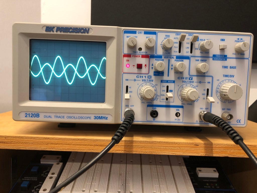
This is the oscilloscope after making the second op amp circuit, which inverted and amplified the signal.
This is an inverting op amp circuit with a potentiometer for the feedback resistor.
This is the inverting signal with a photocell (light determined resistor) replacing the feedback resistor.
The spark fun data sheet for this photocell shows that the maximum resistance, which is the resistance in darkness, is 10k [ohms], and the minimum resistance (full light) is 1k [ohms].
Since this is an inverting circuit, the gain determined by the ratio of Rf/Rin.
Because Rf can go from 1k – 10k [ohms], and Rin was 4.7k [ohms], the minimum gain was approximately .213 (the output sound would be quieter than the input), and the maximum gain would be 2.128 (louder than the input).
Since in the video I didn’t put the photocell in complete darkness or under bright light, the gain was in-between these values.
